


COVNA HK60-Q-T 12v 3 Way 2 Inch Electric Ball Valve
| ON/OFF Type | Feedback: the active contact signal, passive contact signal, resistance, 4-20mA |
| Regulation Type | Input & Output signal: DC 4-20mA, DC 0-10V, DC 1-5V |
| Field operation | The Field, Remote Control Switch Regulation and MODBUS, PROFIBUS Field Bus |
| Voltage Optional | AC110-240V 380V 50/60HZ: DC12V, DC24V, Special Voltage Can be Customized |
| Protection Class | IP65, Explosion Proof Construction Are Available: EX ll BT4 |
| Valve Body | Valve components | ||
| Size Range | DN08-DN80 | Sealing material | PTFE: -29℃~180℃
PPL: -29℃~250℃ |
| Body Material | Stainless Steel | Core Material | Stainless Steel |
| End Connection | Threaded | Stem Material | Stainless Steel |
| Operating Pressure | 1.0MPa~6.4MPa | Applicable media | Control of water, Air, Gas, Oil, Liquid, Steam |
| Structure | 3 Way L-port/T-port | ||

3 Way Ball Valve Flow Diagram: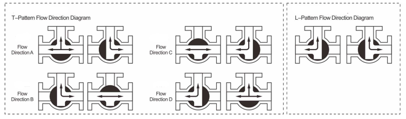
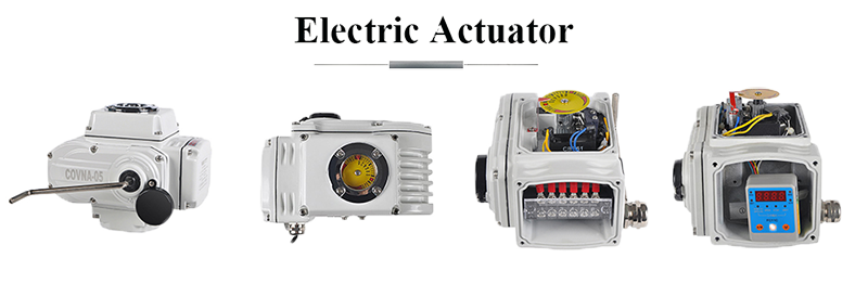
● ON/OFF Type Electric Actuator: 90 degree rotation. AC/DC power supply, signal control and manual override. High torque up to 4000Nm.
● Modulating Type Electric Actuator: Adjust open/close angle from 0 to 90 degree. AC/DC power supply, signal control and manual override. High torque up to 4000Nm.
● Intelligent Type Electric Actuator: Adjust open/close angle from 0 to 90 degree. LED display screen to allow you check the open/close angle easier. AC/DC power supply, signal control and manual override. High torque up to 4000Nm.
| Series | 5 | 10 | 16 | 30 | 60 | 125 | 250 | 400 |
| Torque Output | 50Nm | 100Nm | 160Nm | 300Nm | 600Nm | 1250Nm | 2500Nm | 4000Nm |
| 90° Cycle Time | 20S | 15/30S | 15/30S | 15/30S | 30S | 100S | 100S | 100S |
| Angle Of Rotation | 0-90° | 0-90° | 0-90° | 0-90° | 0-90° | 0-90° | 0-90° | 0-90° |
| Working Current | 0.23A | 0.35A | 0.4A | 0.45A | 0.6A | 1.03A | 1.85A | 2.7A |
| Drive Motor | 50W | 75W | 80W | 100W | 130W | 210W | 285W | 360W |
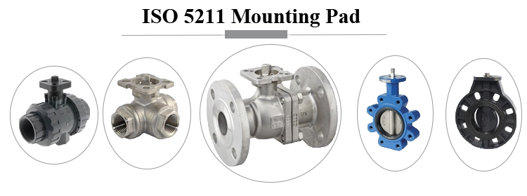
| Mounting Standard | ISO5211 direct mounting | |||||||
| Voltage Options | DC12V, DC24V, AC24V, AC110V, AC220V, AC380V | |||||||
| Input Signal | 4-20mA, 1-5VDC, 0-10VDC | |||||||
| Output Signal | 4-20mA, 1-5VDC, 0-10VDC | |||||||
| Protection Class | IP65 protection class | |||||||
| Ambient Temp | -20 to +60°C | |||||||
| Wiring Diagram | A: ON/OFF type with light indicator signal feedback | |||||||
| B: ON/OFF type with passive contact signal feedback | ||||||||
| C: ON/OFF type with resisance potentiometer signal feedback | ||||||||
| D: ON/OFF type with resistance potentiometer and neutral posistion signal feedback | ||||||||
| E: Regulation type with servo control module | ||||||||
| F: DC24/DC12V direct ON/OFF type | ||||||||
| G: AC380V 3-phase power supply with passive signal feedback | ||||||||
| H: AC380V 3-phase power supply with resistance potentiometer and neutral posistion signal feedback | ||||||||


Technical Parameter of Valve Body:
| Nominal Size | DN15-DN200 | Body Material | PVC, UPV, CPVC, PVDF and PPH |
| End Connection | True Union, Double Union Thread | Structure | T Port / L Port |
| Operating Pressure | 1.0 / 1.6 MPa (10 / 16 bar) | Voltage Tolerance | ±10% |
| Suitable Media | Corrosive media, Water, Air, etc | Temperature Of Media | -5~80℃ (23℉~176℉) |
| Design standard | ISO, DIN, IDF, SMS, 3A | Orifice(mm) | 15, 20, 25, 32, 40, 50, 65, 80, 100 |


_2022_03(1).png)


Purchase Guide:
● Confirm the valve size you need. We offer this motorized PVC ball valve in 1/2in to 4in.
● Confirm the valve body material you need. We offer this motorized PVC ball valve in UPVC, CPVC, PPH and PVDF material.
● Confirm the connection standard. We offer this motorized PVC ball valve in ANSI, JIS, DIN, and UK standard.
● Confirm the pressure and working temperature. Pressure and temperature are the important points and those may affect the cost.
● Confirm the voltage you need. The right voltage could help your valve operate better.
● Tell us your medium. Different medium has different features and we will help you to select the valve basic on the medium requirements
● Confirm the actuator type you need. We have on/off type, modulating type, intelligent type, explosion-proof type, IP68 type and auto return type electric valve actuator for your project.
Any requirements please tell us like core material, sealing material, or connection standard. We could help you to custom the valve you need.
More infomation, please send message to us. Quote will be provided within 2 hours! [email protected]

| Model | 5 | 10 | 16 | 30 | 60 | 125 | 250 | 400 |
| Torque Output | 50Nm | 100Nm | 160Nm | 300Nm | 600Nm | 1250Nm | 2500Nm | 4000Nm |
| 90°Cycle Time | 20s/60s | 15s/30s/60s | 15s/30s | 15s/30s | 30s/60s | 100s | 100s | 100s |
| Angle of Rotation | 0-90° | 0-90° | 0-90° | 0-90° | 0-90° | 0-90° | 0-90° | 0-90° |
| Working Current | 0.25A | 0.48A | 0.68A | 0.8A | 1.2A | 2A | 2A | 2.7A |
| Starting Current | 0.25A | 0.48A | 0.72A | 0.86A | 1.38A | 2.3A | 2.3A | 3A |
| Drive Motor | 10W/F | 25W/F | 30W/F | 40W/F | 90W/F | 100W/F | 120W/F | 140W/F |
| Product Weight | 3kg | 5kg | 5.5kg | 8kg | 8.5kg | 15kg | 15.5kg | 16kg |
| Voltage Option | AC 110V, AC 220V, AC 380V, DC 12V, DC 24V | |||||||
| Insulation Resistance | DC24V:100MΩ/250V; AC110/220V/380V: 100MΩ/500V | |||||||
| Withstand Voltage | DC24V:500V; AC110/220V:1500V; AC380V:1800V 1Minute | |||||||
| Protection Class | IP65 | |||||||
| Installation Angle | Any | |||||||
| Electrical Connection | G1/2 Water-proof Gable Connectors, Electric Power Wire, Signal Wire | |||||||
| Ambient Temp. | -30℃to 60℃ | |||||||
|
Control Circuit
|
A: ON/OFF type with light indicator signal feedback | |||||||
| B: ON/OFF type with passive contact signal feedback | ||||||||
| C: ON/OFF type with resistance potentiometer signal feedback | ||||||||
| D: ON/OFF type with resistance potentiometer and neutral position signal feedback | ||||||||
| E: Regulation type with servo control module | ||||||||
| F: DC24V/DC12V dirct ON/OFF type | ||||||||
| G: AC380V three-phase power supply with passive signal feedback | ||||||||
| H: AC380V three-phase power supply with resistance potentiometer signal feedback | ||||||||
| Optional Function | Over Torque protectors, dehumidify heater, stainless steel coupling & yoke | |||||||
3D Display of Electric Valve:


Committed to global automation application service provider
Privacy Policy
Copyright 2025 GuangDong COVNA Co., Ltd.


.jpg?imageView2/1/format/webp)